Warpage and distortion are not errors – they are physical behaviors defined by the laws of physics. As an engineer or a welder, you are unlikely to change what goes on at a particle level to compromise these laws of physics. Nonetheless, the characteristics and laws of science that describe these important issues can be understood, manipulated, and used to reduce distortion and warpage in welding fabrication.
The physics behind thermal contraction
When the weld pool is created, the metal in that region attempts to increase in size. The adjacent cold metal restricts it. Trapped between the two, the heated metal is deformed plastically – it becomes flat instead of expanding. It then cools down and attempts to return to the previously compressed state, pulling the adjacent base metal with it.
This explains why we have distortion: bowing, angular pull, longitudinal shrinkage, and twisting. The heat-affected zone (HAZ) – the region around the weld that was never melted but was sufficiently heated to be altered – also contains residual stress, locked-in tension and compression that will remain long after the metal has cooled to room temperature. These must be taken care of or they will result in problems downstream.
Optimizing joint design before you strike an arc
The less weld metal you put down, the less shrinkage force you induce. This is not an oversimplification – it’s one of the most basic direct-control levers a fabricator wields.
A double-V groove joint instead of a single-V puts you at almost half the required weld volume, since you’re pushing metal into the joint from both sides. Fillet welds can be particularly easy to overweld: a 10mm fillet where a 6mm would do is not exponentially stronger – it’s simply an unnecessary-to-structural-requirements increase in shrinkage. Weld to spec, not to your instinct about how “making it stronger” works.
The design of the joint also determines how the force is spread over the neutral axis. This is the central plane of your assembly where the tensile forces are exactly mirrored by the compressive forces. Welding in a symmetrical fashion around this axis is one of the surest ways to cancel out distortions.
Sequencing your welds to balance shrinkage forces
The order in which you perform welding is just as important as your welding technique. For instance, if you weld a long, continuous seam on one side of a plate before ever touching the other side, you’ve essentially begun the warping process.
To minimize warping and rework, each increment or “pass” of the weld should be done in the opposite direction of the preceding one. This is called backstep welding. It distributes the heat more evenly and reduces longitudinal shrinkage, which saves you from discovering your piece is warped beyond use.
Skip welding is sort of the same thing as backstep welding because you are also breaking the passes up so that no area winds up getting too hot all in a row. The main difference is that with skip welding you’re hopping around the seam from section to section rather than doing your forward and reverse dance within the same small area.
For structural assemblies, plan a welding sequence that alternates sides. Weld a pass on one face, let the interpass temperature drop to an acceptable level, then weld the opposing face. The opposing shrinkage forces partially cancel each other out. Letting interpass temperature build unchecked by rushing into the next pass doesn’t just risk metallurgical damage – it stacks shrinkage force on top of shrinkage force.
Mechanical restraint and pre-setting
Things like fixtures, jigs, and strongbacks cannot change the fact that when you weld something, the physics of welding will cause the workpiece to be different after welding than before. What those devices do is help ensure that it ends up where you want it after the heat and shrinking and distortion are all over with. For smaller structural parts, clamping it down tight and letting it move where it’s going to move might be an acceptable solution because we’re talking about modest beads bringing together 10-12mm of material over 5-10cm, very small movements. For things where you don’t want or can’t tolerate secondary machining, these are good early steps to minimize heat-induced drifting.
Tack welding plays a role here too. A proper tack sequence locks the joint geometry before you commit to the full weld run, preventing the pieces from drifting under heat. Undertacked joints – especially long ones – will move.
Controlling heat input at the source
The speed at which you work, the amperage you run, and the process you select determine how much heat-affected zone and how much heat input you’ll have.
Stainless makes that obvious. Austenitic grades (like 304, often used in food processing) experience about 50% more thermal expansion from heat and about one-third the thermal conductivity of mild carbon steel. The heat just hangs out in the weld zone because it can’t escape. If you treat it like mild steel, the part will distort something fierce.
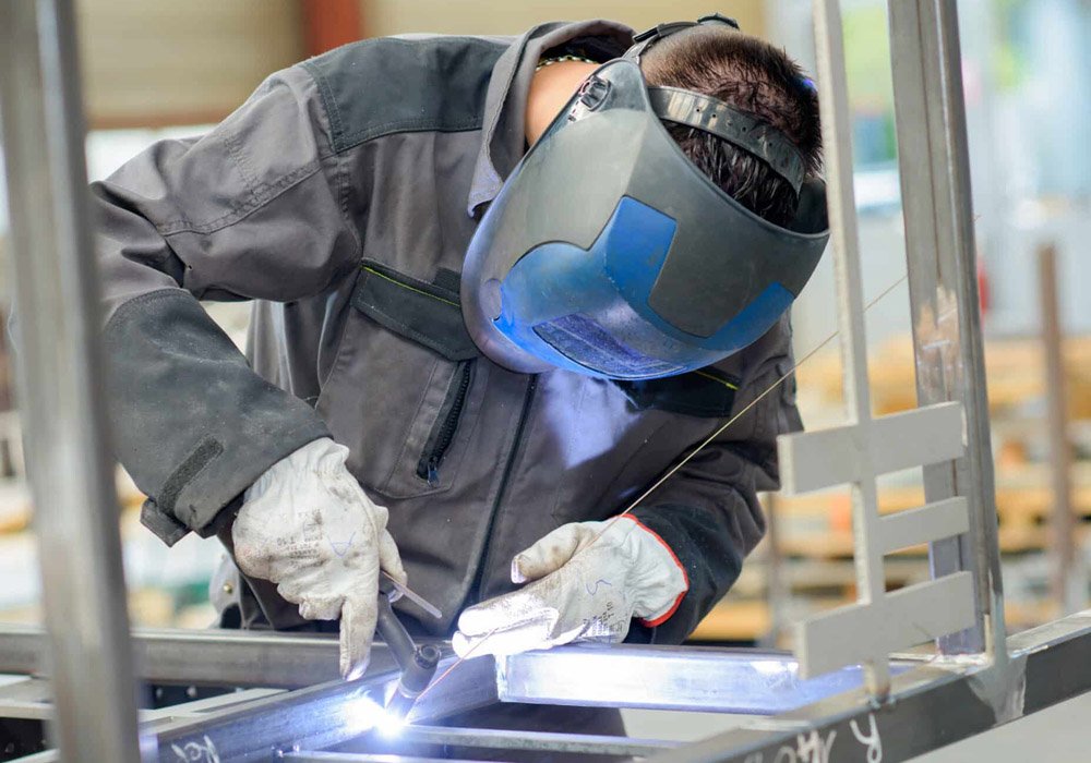
With a material like that, you’ll have tighter control of heating through TIG or pulsed MIG than conventional MIG. And slower isn’t always better. You just want to move at the rate that provides an acceptable dilution or mix of base and filler metal in a consistent manner. Too much heat gets into the part when the torch meanders, and you get a much wider, deeper HAZ than necessary. Too much heat can lead to distortion as well as corrosion and other issues. Try to weld as “cool” as possible to make the weld (not the weld zone) the smallest part of the joint. Fabricators who want to go deeper on process selection and heat management will find that staying current with information about the welding industry is genuinely useful when you’re making decisions about which process fits the material and joint combination.
Correcting distortion after it happens
Despite the best planning, some distortion will come through. The fixes generally fall into mechanical and thermal camps.
Mechanically, methods like peening – essentially hitting the weld bead with a hammer to mechanically stretch it – can help counteract the stress caused by shrinkage. More severe distortion caused by heavy structural welding may necessitate processes like cold pressing or rolling. The effectiveness of these techniques diminishes as welds and base material continue the stress-relief process over time.
Thermal methods, including flame straightening, use heat to expand the part and relieve stress. As it cools and contracts, the part bends back toward flat. Flame straightening involves using an oxy-acetylene torch to heat up a precise area or line on the “convex” side of the distorted part. The “flame-shrink” process cools and contracts the heated area, pulling the weldment back toward straight. It’s not a tool you use to casually roll back days of work into line though; each pass can correct only a portion of a percent of the bend. It’s also a bit of an art to apply correctly. However, flame straightening is one of the most unobtrusive, localized, effective methods for correcting larger distortions in a part that can’t be mechanically managed and must be re-straightened.
Getting ahead of distortion
The fabricators with the fewest reworks are not the best at correcting distortion. They are simply the best at planning to minimize it. It’s the welding joint design, the welding sequence, the fixturing, and the heat control working together. You treat distortion as a known and plan-able variable, and in the end, you will spend far less time correcting work that didn’t have to go wrong in the first place.