Core Technologies in Industrial Instrumentation and Current Measurement
In the demanding world of industrial operations, precision is not just a preference; it’s a necessity. Accurate electrical measurements are fundamental for ensuring safety, optimizing performance, and diagnosing complex system issues. Without reliable data, troubleshooting becomes guesswork, leading to potential downtime and costly mistakes.
Specifically, when dealing with alternating current (AC) and direct current (DC) circuits, the quality of your clamp meter directly impacts the integrity of your diagnostics. We understand the critical need for tools that deliver unwavering accuracy, even in the most challenging environments.
This guide will walk you through the essential aspects of selecting and utilizing accurate AC/DC clamp meters. We will explore everything from understanding core technologies like True-RMS and low-pass filtering to navigating critical safety standards. We will also delve into key selection criteria and best practices for precise field measurements. Our goal is to empower you with the knowledge to choose reliable high-quality digital analog instrumentation that ensures measurement integrity, device durability, and precision diagnostics for preventative maintenance and operational uptime.
Modern industrial environments present a complex tapestry of electrical signals. From traditional sinusoidal AC waveforms to highly distorted signals generated by variable frequency drives (VFDs) and other power electronics, the ability to accurately measure current is paramount. At the heart of accurate AC/DC clamp meters lie several core technologies that enable them to capture these diverse electrical phenomena.
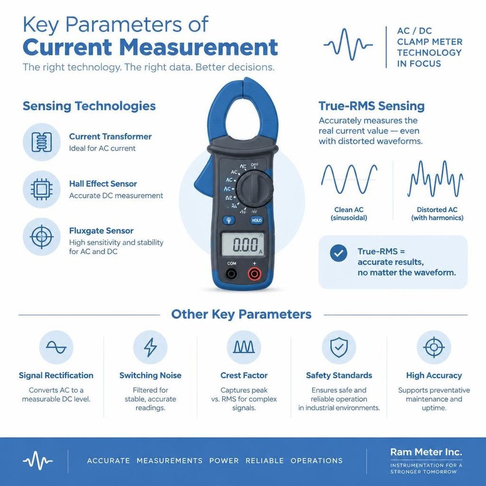
For measuring AC current, clamp meters typically rely on current transformer principles, where the magnetic field generated by the current in a conductor induces a proportional current in the meter’s coil. However, for DC current, and to enhance AC measurement capabilities, more sophisticated technologies are employed. Hall effect sensors are commonly used for DC current measurement. These sensors detect the magnetic field produced by the current flowing through a conductor and convert it into a voltage signal. This allows for non-contact measurement of direct current, a capability traditional current transformers lack. Fluxgate sensing is another advanced technique, offering exceptional sensitivity and stability for both AC and DC measurements, often found in higher-end industrial instruments.
Beyond the fundamental sensing mechanisms, several other factors contribute to the overall accuracy and utility of a clamp meter. Signal rectification is crucial for processing AC signals into a measurable DC equivalent, but its method can significantly impact accuracy, especially with non-sinusoidal waveforms. Switching noise, a common byproduct of modern power electronics, can introduce significant errors if not properly mitigated. Understanding the crest factor—the ratio of a waveform’s peak value to its RMS value—is also vital, as it highlights the meter’s ability to accurately capture the true nature of complex, non-sinusoidal signals.
True-RMS Sensing for Distorted Waveforms in Industrial Instrumentation
In the past, many clamp meters measured AC current by averaging the rectified waveform and then scaling it to approximate the RMS value of a pure sine wave. This “average-responding” method works adequately for clean, sinusoidal AC signals. However, in today’s industrial settings, such pure sine waves are increasingly rare. Modern equipment like VFDs, LED lighting, and switched-mode power supplies introduce significant harmonic distortion, creating non-sinusoidal AC waveforms.
This is where True-RMS (Root Mean Square) sensing becomes indispensable. True-RMS meters accurately measure the effective heating value of any waveform, regardless of its shape. This is critical because the heating effect of an electrical current, which dictates power consumption and component stress, is proportional to the RMS value. An average-responding meter can read up to 30% lower than the actual RMS value on highly distorted signals, leading to misdiagnosis of power quality issues, incorrect load calculations, and potential equipment damage. For example, when troubleshooting a motor controlled by a VFD, a True-RMS meter provides a much more accurate representation of the current the motor is actually drawing, which is vital for proper motor diagnostics and avoiding premature failure. Therefore, for any serious industrial application in October 2026, a True-RMS AC/DC clamp meter is not just a feature, but a fundamental requirement for reliable power quality analysis and accurate heating value calculation.
Low-Pass Filtering and Noise Suppression
Another critical feature for accurate measurements in modern industrial settings, particularly when dealing with variable frequency drives (VFDs) and other inverter-driven equipment, is the low-pass filter. VFDs operate by using pulse-width modulation (PWM) to control motor speed, which generates high-frequency switching noise. This noise can severely interfere with a clamp meter’s ability to accurately measure the fundamental frequency of the AC current or voltage.
A low-pass filter integrated into the clamp meter is designed to attenuate these high-frequency components, effectively “cleaning up” the signal. By filtering out the switching transients and harmonics, the meter can then provide a much more accurate reading of the fundamental frequency and the true RMS value of the current or voltage being delivered to the motor. Without a low-pass filter, the meter might display inflated or erratic readings, making it impossible to correctly assess motor performance, diagnose issues, or verify the VFD’s output. This capability is essential for technicians working on motor control circuits, ensuring that measurements reflect the actual power being delivered rather than a noisy composite signal.
Key Selection Criteria for Accurate AC/DC Clamp Meters
Choosing the right AC/DC clamp meter involves more than just looking at the current range. Several key criteria dictate a meter’s suitability for specific industrial applications and its ability to deliver consistent, accurate results.
One of the most practical considerations is the jaw opening diameter. This specifies the maximum size of a conductor the clamp can encircle. Industrial power cables can be quite thick, so ensuring the meter’s jaw can accommodate them is crucial. A meter with a larger jaw opening, for instance, up to 2.0 inches (50 mm), offers greater versatility.
The dynamic measurement range is equally important. A good clamp meter should offer a wide range, from micro-amps for leakage current detection to thousands of amps for main service panels or motor startup currents. The resolution within these ranges also matters, especially for low-current diagnostics.
Relative zeroing is a feature that significantly enhances DC current accuracy. It allows the user to zero out any residual DC offset before taking a measurement, ensuring that only the actual current flowing through the conductor is measured.
When considering the underlying technology for current measurement, it’s helpful to understand the differences:
| Measurement Type | Common Sensing Technology | Key Advantages | Typical Applications |
|---|---|---|---|
| AC Current | Current Transformer (CT) | Simple, robust, passive | General AC load measurement |
| AC/DC Current | Hall Effect Sensor | Measures both AC and DC, non-contact | Motor diagnostics, battery systems |
| High Precision AC/DC | Fluxgate Sensor | Very high accuracy, low drift | Research, specialized industrial control |
For those seeking robust and precise tools for electrical measurement, exploring reputable providers of industrial test equipment is a wise step. We often look to suppliers of high-quality digital analog instrumentation for our diverse industrial needs.
Resolving Low-Current DC Offsets and Amp-Tip Precision
Measuring low DC currents accurately can be particularly challenging. Several factors can introduce errors, making it difficult to get a precise reading. One common issue is DC magnetization of the clamp meter’s core, which can leave a residual magnetic field that skews subsequent measurements. Additionally, geomagnetic interference from the Earth’s magnetic field or other nearby magnetic sources can subtly influence Hall effect sensors, leading to a baseline offset. This is why features like relative zeroing are so vital; they allow technicians to compensate for these inherent offsets, providing a clean slate for each measurement.
For applications requiring even greater precision in low-current diagnostics, some advanced clamp meters incorporate a feature known as “Amp-Tip” sensing. This specialized function is designed to provide enhanced low-current resolution, often down to 0.1A AC, which is critical for diagnosing issues in control circuits, automotive systems, or low-power electronics where even small current variations are significant. Without such precision, subtle signal drift or minor current draws might go undetected, leading to incomplete or incorrect troubleshooting. By actively compensating for these environmental and inherent sensor biases, these meters ensure that even the smallest DC or low AC currents are measured with confidence.
Dynamic Range, Inrush Current, and Peak Capture
Industrial electrical systems are rarely static. They experience significant fluctuations, especially during startup or under varying loads. An accurate AC/DC clamp meter must possess a wide dynamic range to handle these extremes, from quiescent states to massive current surges.
One of the most critical events to capture is startup current spikes, often referred to as inrush current. When large inductive loads like motors or transformers are first energized, they can draw many times their normal operating current for a very brief period. Capturing these transient events is essential for proper motor diagnostics, sizing protective devices, and understanding system behavior. Many industrial clamp meters feature a dedicated inrush current mode, often with a rapid 30ms capture speed, designed specifically to accurately measure these short-duration peaks.
Beyond inrush, the ability to perform MIN/MAX recording is incredibly valuable. This feature allows the meter to continuously monitor and record the minimum and maximum current (or voltage) over a period, helping to identify intermittent issues, voltage sags, or unexpected load variations. Some meters also offer “peak hold” functionality, which latches onto the highest instantaneous reading, preventing fleeting spikes from being missed. These capabilities are indispensable for comprehensive diagnostics of inductive loads and for ensuring the stability and efficiency of industrial electrical systems.
Safety Standards and Operating Environmental Factors
Working with electricity, especially in industrial settings, inherently carries risks. Therefore, the safety features and robust design of an AC/DC clamp meter are just as critical as its measurement accuracy. A meter’s ability to protect the user from transient overvoltages, arc flashes, and physical hazards is paramount.
International standards, such as IEC 61010-1, define the safety requirements for electrical test and measurement equipment. Adherence to these standards ensures that the device has been designed and tested to withstand specified electrical stresses and environmental conditions. For instance, a meter’s drop resistance is a practical safety and durability feature; a meter that can survive a fall from a typical working height (e.g., 4 to 6.6 feet) is less likely to break and expose internal components, maintaining its safety integrity.
In high-energy environments, such as industrial distribution panels or utility service entrances, the potential for dangerous transient overvoltages is significant. These spikes can be thousands of volts, far exceeding the nominal system voltage. A clamp meter must be rated to safely withstand these transients without failing catastrophically and endangering the user. This is where the concept of Category (CAT) ratings becomes crucial.
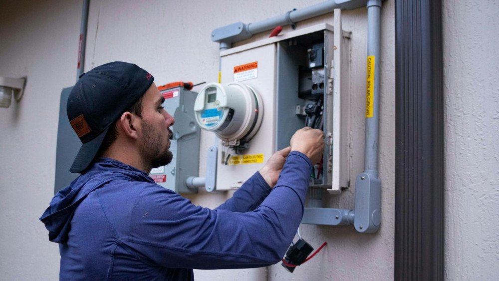
CAT Ratings and High-Voltage Environment Protection
The Category (CAT) rating system is a fundamental safety classification for electrical test equipment, indicating the maximum transient overvoltage a meter can safely withstand in different parts of an electrical installation. Understanding these ratings is essential for selecting the correct clamp meter for the job and ensuring user safety.
- CAT III 1000V: This rating signifies that the meter is suitable for measurements on distribution level circuits, such. as those found in industrial plant equipment, three-phase motors, and feeder circuits. It provides protection against transient overvoltages up to 1000V in these environments.
- CAT IV 600V: This is the highest safety rating for low-voltage installations and is critical for measurements at the source of the low-voltage installation, such as the utility service entrance, electricity meters, or outside and service drop connections. A CAT IV 600V rated meter offers superior protection against very high-energy transient spikes that can occur at these points, which are typically more severe than those found further downstream in a CAT III environment.
For technicians working on facility main distribution panels or other primary power sources, a CAT IV 600V rating is not just recommended, but often mandated by safety regulations. This classification ensures that the meter can safely handle the immense energy available in these circuits, significantly reducing the risk of an arc flash or equipment failure during a transient event. Always match the meter’s CAT rating to the highest category and voltage level of the circuit being measured to ensure proper electrical safety compliance.
Temperature Compensation in Industrial Instrumentation Calibration
Environmental factors, particularly temperature, can have a measurable impact on the accuracy of electrical measurements. While clamp meters are designed for field use across a range of temperatures, it’s important to understand how extreme conditions can affect their performance. Most meters specify an optimal operating temperature range (e.g., 18-28 °C or 64-82 °F) within which their stated accuracy is guaranteed. Outside this range, a thermal drift coefficient typically applies, meaning the accuracy may degrade by a certain percentage per degree Celsius. For example, a meter might specify an additional ±0.1% per °C outside its optimal range.
This ambient temperature range consideration is crucial for maintaining measurement uncertainty within acceptable limits. In environments with widely fluctuating temperatures, such as unheated warehouses in winter or hot outdoor substations in summer, this drift can become significant. To mitigate this, some high-precision instruments incorporate internal temperature compensation circuits. However, for most clamp meters, users should be aware of the effect and consider it when interpreting readings in extreme conditions.
Regular recalibration cycles are also essential to ensure a meter maintains its accuracy over time, regardless of environmental exposure. This typically involves sending the meter to a certified lab for adjustment and verification against NIST traceability standards, usually annually. Understanding the meter’s temperature specifications and adhering to a strict calibration schedule are best practices for ensuring long-term measurement integrity in industrial applications.
Best Practices for Precise Field Measurements
Achieving accurate readings with an AC/DC clamp meter goes beyond just having a high-quality instrument; it also involves adopting meticulous measurement techniques. Even the most advanced meter can provide misleading data if not used correctly.
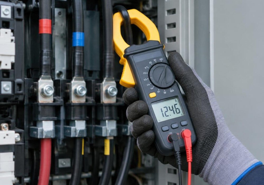
The fundamental rule for any clamp meter measurement is to ensure the conductor alignment is precise. The wire carrying the current must pass perpendicularly through the center of the clamp jaws. If the conductor is off-center or at an angle, the magnetic field sensed by the meter will be distorted, leading to inaccurate readings. Therefore, always strive for perpendicular placement and center the conductor as much as possible.
Crucially, the clamp jaws must fully enclose only a single-conductor isolation. Never clamp around multiple conductors (e.g., both live and neutral wires in an AC circuit, or both positive and negative in a DC circuit) simultaneously. If you do, the magnetic fields will cancel each other out, and the meter will read zero or a negligible current, which is incorrect. Each conductor must be isolated and measured individually.
While clamp meters are non-contact for current measurement, many also offer voltage, resistance, and continuity functions that require test lead contact. For these measurements, ensuring good contact between the probes and the test points is vital to minimize contact resistance, which can introduce errors.
Here are some routine verification steps to ensure consistent accuracy:
- Verify Meter Operation: Before each critical use, test the meter on a known voltage or current source to confirm it’s functioning correctly.
- Zero DC Current: Always use the REL/ZERO function before measuring DC current to eliminate any residual offset.
- Select Appropriate Range: Use auto-ranging or manually select the lowest appropriate range for better resolution, especially for low currents.
- Check Battery Life: Ensure the battery is adequately charged to avoid erratic readings or unexpected shutdowns.
- Inspect Jaws and Leads: Regularly check the clamp jaws for debris or damage, and inspect test leads for frayed insulation or bent connectors.
Frequently Asked Questions About Industrial Metering Solutions
When investing in and utilizing industrial metering solutions, several common questions arise regarding accuracy, selection, and application. Addressing these can help clarify best practices and ensure optimal use of these critical tools for electrical diagnostics.
Why is True-RMS essential for industrial AC/DC clamp measurements?
True-RMS (Root Mean Square) is essential because modern industrial loads frequently generate non-sinusoidal waveforms due to the widespread use of power electronics like VFDs, rectifiers, and switching power supplies. These distorted waveforms contain significant harmonic distortion. An average-responding meter, which assumes a pure sine wave, will provide inaccurate readings, often underestimating the actual current.
True-RMS meters, however, measure the true heating effect equivalent of the waveform, regardless of its shape. This is critical because the heating effect directly relates to power consumption, conductor sizing, and equipment stress. Without True-RMS, you could misdiagnose problems, incorrectly size protective devices, or overlook excessive heating in circuits with electronic switching loads, leading to inefficiency or even equipment failure. It ensures that your measurements reflect the real-world conditions and actual power being delivered.
How does the relative zero function improve DC current accuracy?
The relative zero function is a crucial feature for achieving accurate DC current measurements. Hall-effect sensors, commonly used in AC/DC clamp meters, can be susceptible to minor offsets caused by several factors. These include residual core magnetism (a slight magnetic imprint left on the clamp’s ferrous core from previous measurements), the meter’s internal electronics, and even external ambient magnetic fields (like the Earth’s magnetic field or nearby equipment).
When you activate the relative zero function, the meter takes a baseline reading with no current flowing through the jaws and then subtracts this initial offset from all subsequent measurements. This effectively provides a clean Hall-effect zero offset and compensates for any external magnetic interference, offering a precise baseline calibration. The result is a much more accurate DC current reading, as only the actual current flowing through the conductor is displayed, free from confounding environmental or instrumental biases.
What safety category rating is required for facility main distribution panels?
For measurements on facility main distribution panels, the required safety category rating is CAT IV 600V. This is the highest safety category for low-voltage installations and is specifically designed for measurements at the origin of the installation, where the highest energy transient spikes can occur.
These locations, such as the service entrance, utility meters, and primary overcurrent protection devices, are exposed to the most severe transient overvoltages that can be generated by lightning strikes, utility switching, or large inductive load changes on the grid. A CAT IV 600V rating ensures that the clamp meter is built with sufficient insulation, creepage, and clearance distances to withstand these extreme transient events, providing robust transient spike protection. Using a meter with a lower CAT rating in these environments significantly increases the risk of meter failure, arc flash, and severe injury to the user. Always prioritize electrical safety compliance by selecting the appropriate CAT IV rated instrument for these high-energy applications.
Conclusion
In the dynamic and often challenging landscape of industrial operations, the accuracy and reliability of your measurement tools are non-negotiable. This guide has underscored the critical importance of selecting and properly utilizing accurate AC/DC clamp meters. We’ve explored how advanced technologies like True-RMS sensing and low-pass filtering address the complexities of modern electrical signals, from distorted waveforms to high-frequency noise.
We’ve also highlighted the practical criteria for selection, such as jaw opening and dynamic range, alongside specialized features like relative zeroing and inrush current capture that enhance diagnostic capabilities. Crucially, we emphasized the paramount role of safety standards, particularly CAT ratings, in protecting personnel in high-energy environments.
By adhering to best practices for precise field measurements and understanding the nuances of these sophisticated instruments, professionals can ensure measurement integrity and prolong device durability. Investing in and correctly using accurate AC/DC clamp meters empowers technicians with the ability to perform precision diagnostics, facilitate preventative maintenance, and contribute directly to enhanced operational uptime in any industrial setting.